International Journal of Epidemiology And Public Health Research
OPEN ACCESS | Volume 9 - Issue 1 - 2026
ISSN No: 2836-2810 | Journal DOI: 10.61148/2836-2810/IJEPHR


Sergio Palandri
Radiographer – Umberto I Hospital Ordine Mauriziano – Turin - Italy.
Corresponding author: Sergio Palandri, Radiographer – Umberto I Hospital Ordine Mauriziano – Turin - Italy.
Received: June 28, 2025
Accepted: July 04, 2025
Published: July 09, 2025
Citation: Palandri S. (2025) “System Expanded for Postural Analysis (S.E.P.A.): the Upgrade to S.E.P.A. Plus”. International Journal of Epidemiology and Public Health Research, 6(5); DOI: 10.61148/2836-2810/IJEPHR/155.
Copyright: © 2025. Sergio Palandri. This is an open access article distributed under the Creative Commons Attribution License, which permits unrestricted use, distribution, and reproduction in any medium, provided the original work is properly cited., provided the original work is properly cited.
Background/Aim
In June 2024, an article was published about a postural analysis system called S.E.P.A.
The aim of this article is to describe the improvements made to S.E.P.A., suggested by its use and by the comparison with the professional who used it, thus leading to the creation of the new S.E.P.A. Plus, thus realizing the hope expressed in the article.
Materials and Methods
The main structure, the secondary structure and the main plate have been completely renewed, as well as the supports for the laser levels and webcams.
Results.
Very encouraging results have been obtained from the first uses, in terms of greater stability, practicality and precision in laser levels positioning, as well as a reduction in assembly/disassembly times.
Conclusions
The improvements made undoubtedly seem promising. However, its systematic use is now necessary to verify its actual effectiveness.
In July 2024, an article was published in the literature relating to a new postural analysis system, called S.E.P.A. [1]. A particularly significant aspect of the article, which is recommended for a detailed and precise description of the hardware, software and proposed method, is the underlining of the need, as reported in the conclusions, for a systematic use of S.E.P.A. and the comparison with the professionals who use it, in order to highlight critical issues, confirm strengths and thus be able to improve the system itself, an aspect that is even more relevant in the current context where postural analysis has established itself in an important role not only in the diagnostic and follow-up field, but also in the preventive one, although this is still little practiced given a non-negligible lack of generally shared standards, as can be inferred from some literature articles [2-8].
The aim of this work is, therefore, to present the changes made to the S.E.P.A. system, dictated by its use, which led to the creation of its new version, called S.Ep:A. Plus.
Methods
The main critical issues that S.E.P.A. has highlighted in its use, concern its structural characteristics and the improvement actions have been concentrated on these. In particular:
On The Main Structure
As a consequence of the various and successive implementations that led to the creation of S.E.P.A., the two main poles that constitute the load-bearing structure of the system, had the constituent segments no longer perfectly aligned, generating translation problems of the laser levels and webcams.
Another critical aspect lay in the complexity of fixing between the poles and the support plate, due to the need to keep the system as stable as possible.
It was therefore decided to completely change both poles and switch to a commercially available model, used to support laser levels for internal construction sites, consisting of segments 600 mm long and 35 mm in diameter, joined together with threaded 5/8”-11 pivots and holes.
The 4 segments used for each pole were then fixed to the support plate using two 5/8”-11 bolts 25 mm long, screwed into a specially prepared threaded hole on the plate, with the interposition of a steel washer with an external diameter of 42 mm. The bolts screwed into the lower side of the plate thus protrude from its upper profile by approximately 15 mm, allowing the poles to be screwed in via their threaded hole at the lower end, as shown in the assembly and details reported in Fig. 1 on the right.
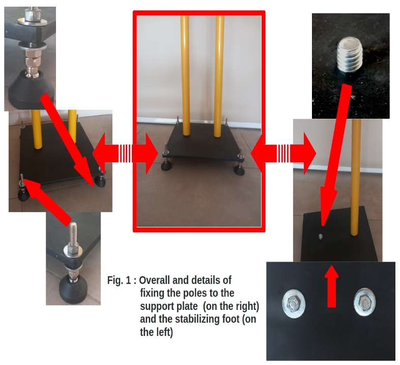
This type of fixing, which in itself constitutes an angular stability system, allows the fixing bolts to be joined to the support plate and the poles, creating an overall more stable structure as it does not enable movements between the bolt and the plate as well as the ones between the bolt and the pole, which could quickly result in the appearance of backlash that would make the entire structure unstable.
The poles were then connected at the top by a new specially designed and made joint, derived from the previous existing joining bracket, which will be described later, using thr two threaded terminal pivots of the two poles, now blocked with 5/8”-11 nuts.
The support feet have also been completely upgraded, adopting a model commercially available, which presents significant improved characteristics:
- larger support diameter (now 50 mm)
- larger diameter threaded pivot (now 8mm)
- greater length of the threaded pivot (now 50 mm)
- threaded pivot that can be angled with respect to the foot
as shown in the assembly and the details reported in Fig. 1 on the left.
On The Support Structures of Laser Levels and Webcams
The change in the diameter of the poles of the main structure has inevitably impacted the support brackets of the laser levels and webcams, designed and built for poles with a diameter of 10 mm less.
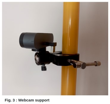
We therefore took inspiration from this data to make the supports of the laser levels and webcams more efficient, using commercially available products as shown in Fig. 2 for the supports relating to the laser levels and in Fig. 3 for the supports relating to the webcams.
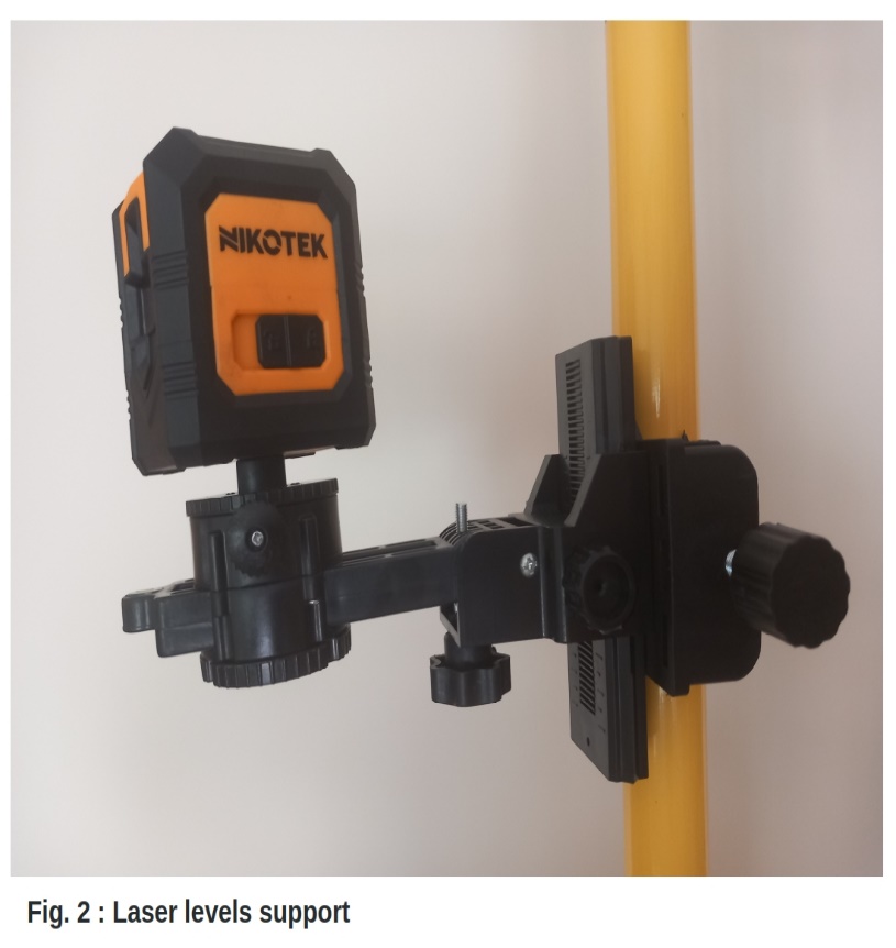
It should be noted that both types of support are of the clamp type, with assembly independent from that of the main structure and therefore mountable/movable with the main structure already assembled.
A further feature of the new supports lies in the possibility of performing precision movements allowing for simple and precise centering of the laser levels and rapid and easy positioning of the webcams. In particular, it should be emphasized that this option is now also available for the WF which has been removed from the support plate and placed on the poles of the main structure.
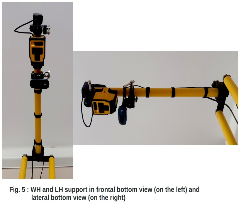
The change in the main supporting structure has also affected the secondary support structure relating to the WH and the LH.
First of all, the 500 mm vertical connecting segment that joined the support arm of the WH and the LH to the main structure has been eliminated, now replaced by the greater height of this (2.4 m against the previous 2.0 m).
The horizontal arm was also replaced, now using a segment of a similar type to those of the main structure, 600 mm long and with a diameter of 35 mm.
The supports of WH and LH were consequently adapted, using a new type identical to the one used for WF and shown in the previous Fig. 3.
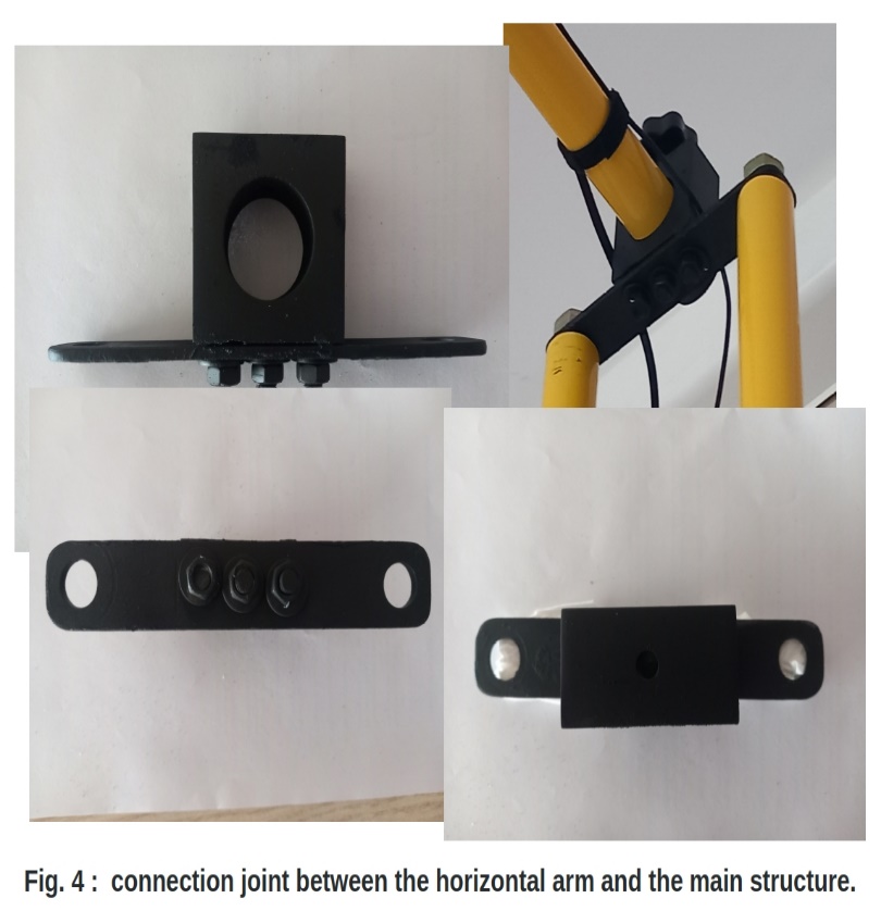
To allow a stable connection between the horizontal arm and the main structure, a plexiglass joint was designed and created, as earlier mentioned, which was permanently connected to the union bracket of the two poles of the main structure previously existing, as shown in Fig. 4.
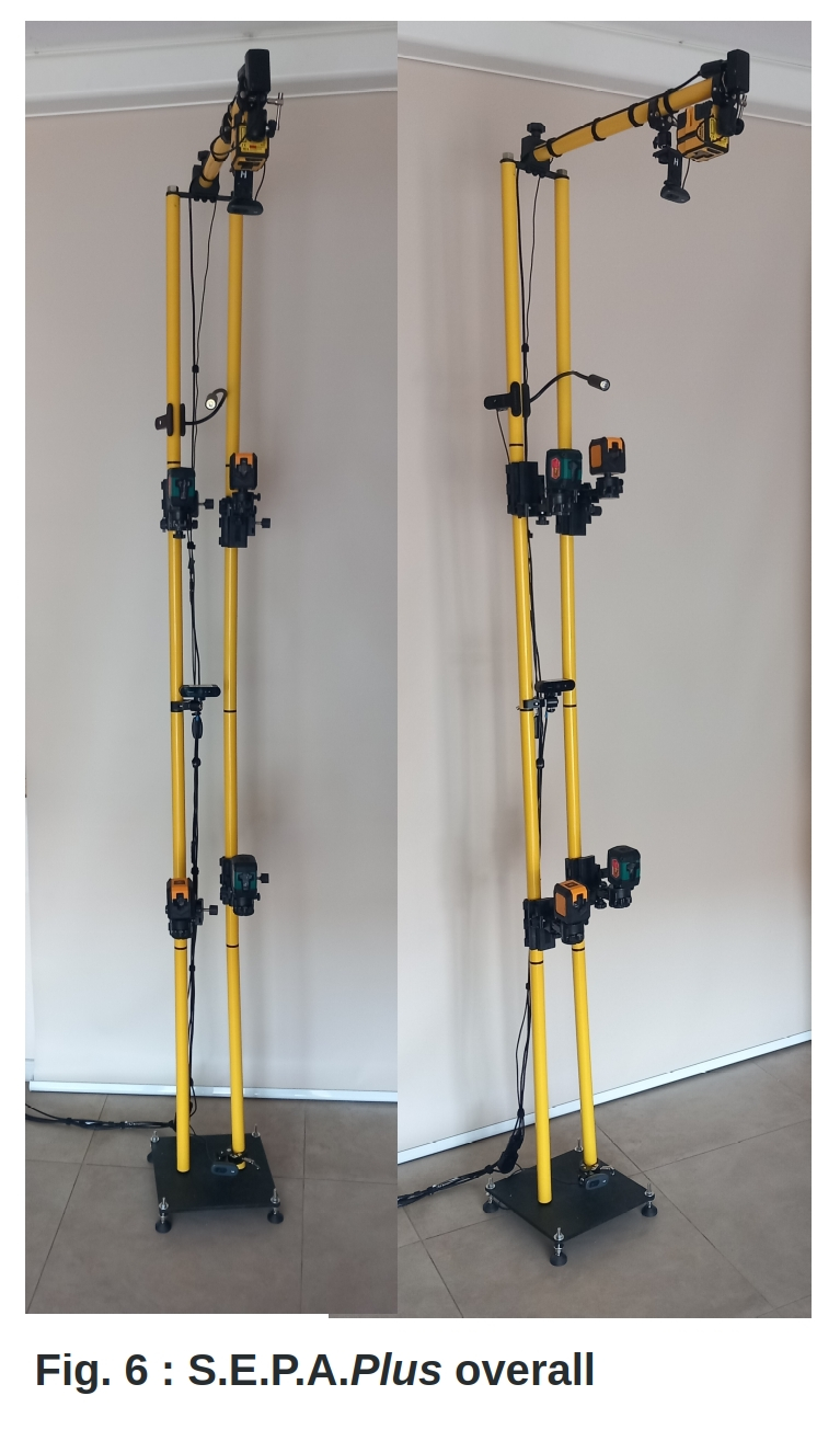
In Fig. 5, the new horizontal arm is visible with WH and LH fixed via the new supports, while Fig. 6 shows the overall view of the new S.E.P.A.Plus.
All the features of S.E.P.A. not analyzed in this article, such as the software, the postural analysis protocol, the scanner for acquiring the feet standing print and others, have been directly integrated into S.E.P.A Plus without modifications and are therefore available exactly as in S.E.P.A. Therefore, refer to the aforementioned article for their description [1] as they belong to S.E.P.A. Plus for all intents and purposes.
Results
The first tests carried out with S.E.P.A.Plus have provided encouraging results with a clear reduction in assembly/disassembly times (approximately 50%), greater stability, greater simplicity and flexibility in use and greater precision in the positioning of the laser levels traces on the subject under examination.
Discussion
From the preliminary use of S.E.P.A.Plus, some advantages have undoubtedly emerged, such as e.g.:
However, even if limited and surmountable, disadvantages have also emerged, such as e.g.:
1. the need now for a small ladder for complete assembly, since the poles are 2.4 m high overall
2. the weight which always remains a non-negligible factor, especially for travel on public transport and by a single operator
Conclusions
S.E..P.A.Plus seems to represent a good upgrade of S.E.P.A., decidedly significant and with interesting and promising features. However, as for S.E.P.A., only its systematic use and the comparison between the designer and the professionals who will use S.E.P.A. Plus, will be able to provide feedback on the actual achievement of the objectives that the improvements made had set themselves, as has happened previously, leading to the creation of S.E.P.A. Plus.
Abbreviations
LH: laser level head
WF: webcam feet
WH: webcam head
Acknowledgement
Once again an heartfelt thanks is due to Dr. Daniela Fandavelli for her indispensable professional contribution to the enhancement that led to the S.E.P.A.Plus, as well as her precious friendship.
Declarations
The author declares to have no conflict of interested.
All figures were created personally by the author.


Open Access By Aditum Open Access Journals id licensed under Creative Commons Attribution 4.0 International License. Based On a Work at aditum.org